Next: Graphical Interface Up: Real Experiments Previous: The Robot
Since we do not focus our research on the Vision system of the robot, we did not intend to develop a Vision system capable of recognizing complex objects, but just a very simple type of landmark. The simplest type we thought of was barcodes.
Landmark labels have a common part of five vertical black bars, to indicate that it is a
landmark, and at the right side of the bars, a vertical binary
codification with black and white squares. The binary code is composed
of five squares (black meaning 1, white meaning 0), so we have 32
different codes. However, codes 0 and 31 are not used, as they give
many problems when trying to identify them, so we have a
total of 30 different codes, which is enough for our environment.
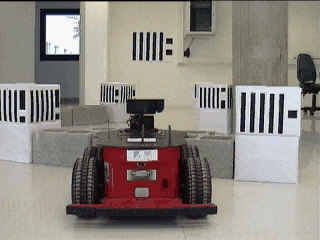
We have used boxes with the same landmark label on their four sides so the
Vision system is able to detect the landmarks from any perspective.
The labels are printed on DIN A4 papers, and the dimensions of the
boxes are 30![]() 30
30![]() 40 (length
40 (length![]() width
width![]() height), having the labels at
the top of each side.
Examples of such landmarks are shown in Figure 6.3.
height), having the labels at
the top of each side.
Examples of such landmarks are shown in Figure 6.3.
![\includegraphics[width=12cm]{figures/lmks2pics}](img277.png) |
The algorithm for recognizing these landmarks is based on the fact that the pattern of a series of alternated black and white bars of equal width is very unusual. First of all, the image is binarized, since it is in gray scale, and the algorithm needs to have pure black and white images. A close operation is also applied. This operation is useful for removing noise from the image. Once the binarization and the close operations are done, the algorithm starts scanning the image line by line, looking for the pattern of black and white bars. When it finds such a pattern, it scans vertically the binary code to identify which landmark has been detected. Depending on the lighting, a landmark can be detected using a binarization threshold, but not detected for other thresholds. Thus, this scanning process is done several times with different thresholds. Once the whole image has been processed with all the thresholds values, the information of all detected landmarks is sent to the Navigation system. A flowchart of the process is shown in Figure 6.4.
Although the robot is equipped with two cameras, we are now processing only the images of one of them, as we have not yet finished the implementation of the stereo vision algorithm. This algorithm would use the images from both cameras to compute the distance to the detected landmarks. However, we simulate that we already have this stereo vision algorithm. To do so, we have designed the landmarks so that all of them have the same size. This way, knowing the height of the bars (in pixels of the image) of a landmark, the distance from the robot to that landmark can be computed. The heading is taken as the angle to the central point of the label. However, even with the robot stopped, and due to illumination conditions, the image processing algorithm does not always detect the landmarks in the same place (it can vary some pixels). Thus, the computed distances and angles have some imprecision.
Since the quality of the cameras is not very good, the Vision system has some problems with recognizing landmarks that are far from the robot. To have a robust recognition system, we have set that it only informs about the landmarks that are within a distance of 3 meters around the robot. However, even if a landmark is in this ``visible area'', the Vision system sometimes misidentifies it. To solve this problem, we require that a landmark has to be recognized in several subsequent frames with the same code before informing about its detection.
But even this last requirement is not always enough to give correct landmark identification. To add more robustness to the Vision system, the detected landmarks are checked against the Visual Memory (see Chapter 4 for a detailed description of the Visual Memory). For each landmark in the list of detected landmarks, two checks are done. First, we check that the detected landmark is not in a location close to another landmark stored in the Visual Memory (i.e. the distance between the two locations - one given by the Vision system and the other one stored in the Visual Memory - is below a threshold). If this is the case, and the code of the landmark differs from the one given by the Vision system, we replace the code of the detected landmark by the one stored in the Visual Memory on that location. If the code is the same, then the location given by the Vision system is assumed to be correct, and it replaces the location stored in the Visual Memory. Secondly, we check that the detected landmark is not stored in the Visual Memory at a very different location than that given by the Vision system. If this is the case, and the location stored in the Visual Memory lies in the view field of the camera, this location is given as the location of the detected landmark. If the location does not lie in the view field, the landmark is ignored. Finally, if the detected landmark is neither stored in the Visual Memory nor located close to another landmark, it means that it is a new landmark, and it is added to the Visual Memory. Table 6.1 summarizes the actions taken in each situation. We indicate the information about the landmark (code and location) that is finally sent to the Navigation system, and how the information of the Visual Memory is modified. The subscript VS stands for the information given by the Vision system, while the subscript VM refers to the information stored in the Visual Memory.
| Close location | Different location | |
| Same ID |
-Right recognition- return Update location in VM |
-Wrong recognition- if return else ignore landmark |
| Different ID |
-Wrong recognition- return Update location in VM |
-Right identification- return Add to VM |
Although this check adds robustness to the Vision system, it may have undesired effects in some situations, since it gives more importance to the information stored in the Visual Memory than to that coming from the Vision system. For instance, if the location of a correctly detected landmark differs too much from its location stored in the Visual Memory, not because of an error of the Vision system, but due to the imprecision of the stored location, it will not be updated, although it should be. Another problematic situation would arise if the robot were moved to another location, without it noticing it (what is known as the ``kidnapping problem''). From the new location, the Vision system would detect some landmarks, but their locations would not match at all with the locations stored in the Visual Memory, and, therefore, they would not be updated either. The first problem can be solved by changing the imprecision threshold above which the landmarks are removed from the Visual Memory, so that it only keeps those landmarks whose location is very precisely known. However, there is no way to solve the ``kidnapping problem''. The only way to handle it would be to have a better Vision system, so that it would not need to check the locations with the Visual Memory. Since we still do not have such a Vision system, and in our experiments the robot is never ``kidnapped'', we rely on the Visual Memory.
With all these provisions, landmarks are always correctly identified, therefore there is no uncertainty about the presence of landmarks, although there is imprecision about their exact location.
The fact of the Vision system being only capable of recognizing landmarks not further than 3 meters from the robot, together with the assumption of the initial visibility of the target, restricts the possible environments on which we can experiment. In order to be able to test the Navigation system on more interesting (larger) environments, we have a special landmark label that is considered as the target and can be seen from 7-8 meters. This landmark label is of the same type as the rest, but has a larger size (DIN A1), and when computing the distance from the robot to it, this is taken into account. In Figure 6.5 this larger target landmark is shown (there are four ``standard'' landmarks, plus the larger target, placed higher than the others).
© 2003 Dídac Busquets
![\includegraphics[width=12cm]{figures/vision}](img278.png)